Power Supply for Piezoelectric Actuators
The inverse piezoelectric effect of appropriate crystal materials allows the direct generation of mechanical displacements or forces by electrical voltages. The achievable relative deformation is around 0.2 %. The force generation depends on the stiffness of material. Piezoelectric actuators are able to generate high pressure up to 35 N/mm2, in comparison to approx. 0.02 N/mm2 of electromagnetic actuators. Very high dynamic response is one of the characteristic features of piezo actuators. These actuators are suitable for static as well as for dynamic applications. Fuel injectors, e. g., are one of the important and well known application for quasi-static mode with the piezo actuator opening the injector valve for a very short moment [14]. The ultrasonic vibration or ultrasonic piezoelectric motors are applying the dynamic mode of operation [12], [13].
The piezoelectric actuators are used in various applications:
- Wire bonding, generation of ultrasonic or sonic vibrations, cutting and drilling tool assistance, active wedges
- Injectors, droplet generators
- Positioning of optical mirrors, tools, lenses, focusing and scanners
- Ultrasonic piezoelectric motors
For more than fifteen years LEA has been focusing on the development of power supplies for piezoelectric actuators and their model-based control [3], [4], [5]. Thus, a solid experience on driving resonant-type piezoelectric actuators has been gained. Harmonic elimination PWM techniques and an appropriate filter must be considered, if the excitation voltage should be subjected only by a minimum of harmonics to increase the lifetime of the piezo stacks [9], [10]. The challenge of an appropriate power supply design arises from following reason
- Due to the piezoelectric effect, the design of the output filter of a power supply is highly influenced by the mechanical oscillation system. A closer inspection reveals that the electrical behavior depends on the frequency-dependent interactions between the actuator and the load.
- Piezoelectric actuators are known to exhibit a distinct capacitive behavior. The piezoelectric capacitance should be an inherent part of the output filter. However, the capacitance of the piezoelectric actuators varies with temperature thus is also dependent on operating conditions.
- Both the real power and reactive power are delivered by the power supply to the piezoelectric actuator. The high operating frequency results in high switching losses of the power supply and EMI issues might to be solved. Therefore, the power ratio and the efficiency depend on the working point of the piezoelectric actuator.
Electronic power supplies for piezoelectric systems have been well studied and applied using different kinds of resonant converter concepts. A resonant inverter with series parallel resonant filter (LLCC-filter) shows advanced characteristics and best suited properties in respect to efficiency, stationary and dynamic behavior, and also to control and commissioning efforts. The drawbacks of these resonant inverters are the large volume, heavy and costly magnetic components of the resonant filter like the transformer and inductor, especially in case of driving piezoelectric actuators in the range of some kW.
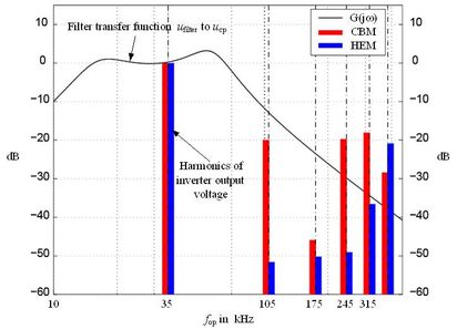
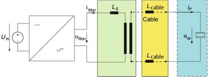
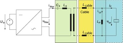
Therefore, power converters which do not require heavy inductors are of great interest. Size and weight of the magnetic components could be reduced by a carrier-based PWM (CBM) converter with LC-filter (Fig. 1). Investigations show that LC-PWM inverters are more suitable for weakly damped piezoelectric vibration systems such as bond sonotrodes, where none or small reactive power is delivered at the operating point by the inverter [14]. Thanks to the high switching frequencies, the inductivity Ls can be decreased significantly in comparison to those used in resonant filters [12]. This results in smaller and lighter components. However, the high switching frequency of PWM inverters consequently results in higher switching losses and might be in conflict with EMC issues. To overcome these drawbacks, the proposed LLCC-PWM inverter was developed to excite the high-power piezoelectric actuator, where a LLCC-filter circuit is utilized and operated in PWM controlled mode (see Fig. 2) [1], [9], [10]. A PWM method with calculated switching angels eliminates selected number of harmonics (HEM) and influences the frequency spectrum of the converter output voltage ufilter. In conjunction with the band-pass characteristic of the LLCC-filter the HEM method will result in lower total harmonic distortion (THD) of the actuator voltage uCP as with CBM (cp. Fig. 3).
The novel solution offers significant advantages to improve the performance of the power supply as follows.
- Reactive power of the piezoelectric actuator is compensated locally, by placing the inductor Lp close to the actuator.
- The output filter shows optimized performance at minimized volume and weight, compared to the classical resonant inverters.
- THD of the piezoelectric actuator voltage ucp is reduced without increasing the switching frequency.
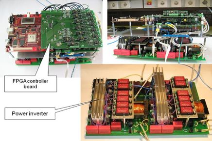
The proposed LLCC-PWM inverter (Fig. 4) was employed for driving a high power airborne piezoelectric brake actuator in an EC-funded project PIBRAC [2], [3], [4], [5], [7]. Other potential fields of application of LLCC-PWM inverters are: superimposed sonotrodes assisted ultrasonic drilling, cutting, chiseling, and milling of tooling machines or atomizers for the production of fine granular powder.
References:
| [1] | R. Li, N. Fröhleke, C. Kauczor LLCC-PWM-Converter Patent: PCT/DE2007/000773, filed under 10 2005 021 559.1, May 2006 |
| [2] | R. Li, N. Fröhleke, H. Wetzel, J. Böcker, S. Ouchouche, E. Agostini, J.-T. Audren Power Supply and Control Scheme for an Airborne Piezoelectric Brake Actuator Proc. of 10th International Conference on New Actuators, ACTUATOR 2006, Bremen, Germany, 2006 |
| [3] | R. Li, N. Fröhleke, H. Wetzel, J. Böcker Power Supply and Control Scheme for an Airborne Piezoelectric Brake Actuator International Power Electronics and Motion Control Conference 2006, IPEMC-2006 on August 13-16, Shanghai, China, 2006 |
| [4] | H. Wetzel, N. Fröhleke, J. Böcker, S. Ouchouche, D. Bezanere, F. Cugnon Modelling and control of a multi-mass ultrasonic motor for airborne applications IECON-2006, November 7-10, Paris, France, 2006 |
| [5] | R. Li, N. Fröhleke, J. Böcker Design and Implementation of a Power Inverter for a high Power Piezoelectric Brake Actuator in Aircrafts 9th Brazilian Power Electronics Conference, Blumenau, Brazil, 2007 |
| [6] | R. Li, N. Fröhleke, J. Böcker Analysis and Design of a Novel Three-Level LLCC Inverter supplying an Airbone Piezoelectric Brake Actuator 38th Annual IEEE Power Electronic Specialists Conference, Florida, USA, 2007 |
| [7] | H. Wetzel, R. Li, N. Fröhleke, J. Böcker Piezoelektrische Flugzeugbremse Workshop Entwurf mechatronischer Systeme 2007, Paderborn, Deutschland, 2007 |
| [8] | R. Li, M. Lönneker, N. Fröhleke, J. Böcker Design of Power Supply for driving High Power Piezoelectric Actuators IAS, Edmonton, Canada, 2008 |
| [9] | R. Li, N. Fröhleke, J. Böcker LLCC-PWM Inverter for driving High Power Piezoelectric Actuators EPE-PEMC, Poznan, Poland, 2008 |
| [10] | T. Schulte Stromrichter- und Regelungskonzepte für Ultraschall-Wanderwellenmotoren Fortschritt-Berichte VDI, Reihe 21, Nr. 363, VDI Verlag, Düsseldorf, 2004 |
| [11] | J. Maas Modellierung und Regelung stromrichtergespeisten Ultraschall-Wanderwellenmotoren Fortschritt-Berichte VDI, Reihe 21, Nr. 278, VDI Verlag, Düsseldorf, 1998 |
| [12] | C. Kauczor, N. Fröhleke Inverter Topologies for Ultrasonic Piezoelectric Transductors with High Mechanical Q-Factor Proc. of IEEE Power Electronics Specialists Conference (PESC04), Aachen, Germany, 2004 |