Modular Multi-Level Inverter for Electric Mobile Drive Systems

(Original title: Modularer Multilevel-Inverter für elektromobile Antriebssysteme)
The research project is funded and supported by the German Federal Ministry of Education and Research (BMBF) within the framework of the research initiative ‘SME-innovative: Electronics and autonomous driving’.
Project acronym: MIELAS
Funding period: 3 years (2020/01/01 – 2022/12/31)
Project partner: IMG Electronic & Power Systems GmbH, elerra motiv GmbH
Project profile: https://www.elektronikforschung.de/projekte/mielas
Motivation
The main challenges for both battery electric and plug-in hybrid vehicles are to achieve a high drive power in a small installation space and with low mass, to maximize the efficiency of the power conversion from the energy storage to the mechanical drive shaft and also to ensure a high and safe availability of the drive system in terms of fail-safe or fail-operational capabilities. An essential component for this is the traction converter, which converts the DC voltage provided by the energy storage (battery / fuel cell) into an AC voltage suitable for the traction motor (usually 3-phase three-phase system). In addition to the pure power conversion, the converter also contains a logic and supervison level for controlling and monitoring the entire drive system.
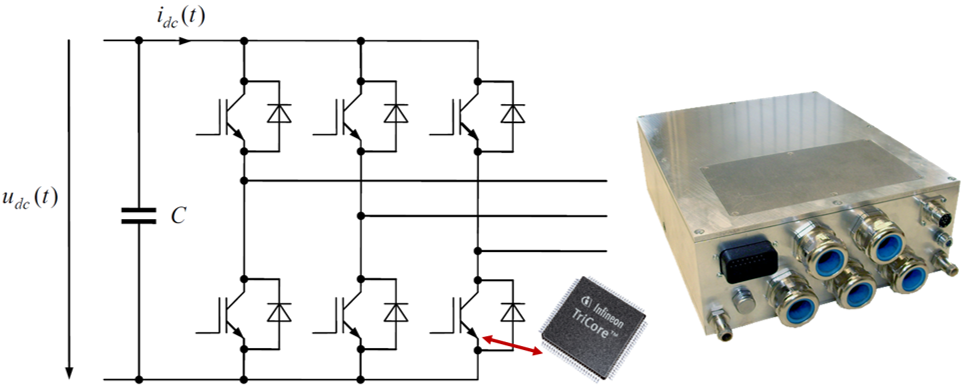
Today, the automotive standard inverter is considered a 2-level B6-bridge consisting of IGBTs semiconductors monitored and controlled by a classical microcontroller (see Fig. 1). While this design is considered cost-effective, it’s lacking flexibility in case of (partial) system errors as well as power scaling for different target applications. Moreover, the motor and inverter efficiency are below optimal mainly due to large amount of voltage and current harmonics injected due to the 2-level architecture.
Project Objectives
The objective of this project is to achieve a significant innovation leap in terms of efficiency, modularity, power density and operational reliability compared to the state of the art. This will be realized by combining modular multi-level technologies (MMT), novel power electronic semiconductors as well as control and monitoring concepts based on Field-Programmable Gate Arrays (FPGA) into a concept for future traction converters.
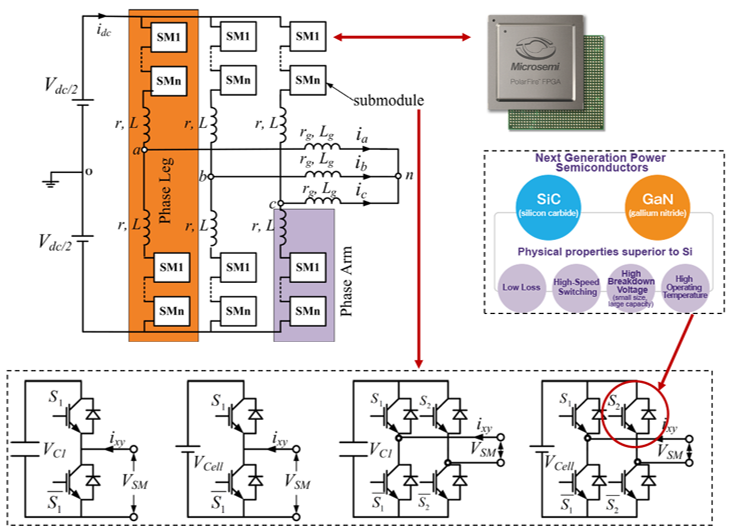
A simplified schematic diagram is depicted in Fig. 2. It shows the classical modular multilevel topology (modular-multilevel-converter - MMC), which consists of dedicated switching cells (submodules). The serial connection of the cells in a converter string increases the manageable maximum DC link voltage on the DC side and the number of switching levels at the converter output for given power semiconductors. The latter improves the voltage waveform towards the desired sine wave and, thus, reduces the losses in the motor to be driven. The topology itself also shows an increased efficiency due to the reduced switching stress on the semiconductors. The modularity also allows several inverter types to be derived with regard to different power levels in the sense of a modular system. Furthermore, the topology has an inherent fail-operational capability, as faulty switching cells can be bridged and the system can continue to operate (at reduced power) even in the event of a fault.
Another innovation driver is the use of new types of wide-bandgap devices (WBG), especially silicon carbide (SiC) and gallium nitride (GaN). Compared to the usual silicon-based IGBT semiconductors, significantly faster switching processes can be realized, which reduces the switching losses and also allows a higher average switching frequency. In addition, the latter again enables loss-reduced control of the motor to be driven. The FPGA-based control of the drive system rounds off the overall package: This is largely independent of the hardware platform used, so that an FPGA design in VHDL, once developed, has a significantly longer lifetime than comparable approaches based on standard microprocessors. FPGAs also have a significant advantage due to the possibility of parallel processing of several tasks, for example for the control of complex power electronic systems. Furthermore, FPGAs allow direct measurements of phase currents and phase voltages using delta-sigma modulators, which allows complex methods for monitoring the connected motor (e.g. highly dynamic fault detection or model-based temperature measurement). This makes it possible to reduce the degree of over-dimensioning of the system in the design phase to safeguard against unusual operating conditions, which in turn increases the power density and leads to resource savings.
During the project, a lab demonstrator will be developed and manufactured for experimental testing targeting real world automotive usage. The key figures of the demonstrator are:
- Continuous apparent power: 200+ kVA
- DC link voltage range: 800 ... 900 V
- Power density (at least): 16 kVA/litre or 15 kVA/kg
- Inverter efficiency (at rated power): 98 %.
- Protection class (minimum): IP65
- Switching frequency: Adaptive and variable (up to 20 kHz or more)
- Cooling: water-glycol
- I/O: CAN interface, position encoder interface, etc.