Microgrid-Labor


Typical microgrid research is very specific and test environments are designed for a specific scenario. Control strategies or Microgrid components should be tested in cases for which testing in real grids would be unreasonable or dangerous. These scenarios include fault ride through situations, blackouts, brownouts.
This requires a flexible test environment.
The microgrid laboratory at Paderborn University consists of 16 inverter nodes with a high amount of configuration flexibility. The grid node inverters have a nominal power of 250 kVA per device. With a total installed power of 4 MVA, the microgrid laboratory is able to emulate 2 MVA of loads and 2 MVA of sources. This capability enables it to emulate power flows matching real grid components with relatively low scaling factors.
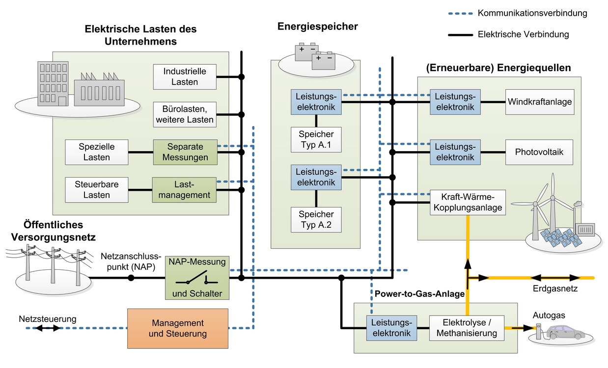
As shown in Fig. 2, the grid node inverters are individually connectable to one of six separate grids. The common DC-link, shown in blue, is a 3-level DC-rail with a total voltage of up to 800 V supplying all inverters.
It is fed from public grid through a controlled rectifier.
As all grid nodes are bidirectional, the power flow is fed back to other inverters and the power supply from the grid is only needed to cover the conversion power losses. It is also possible to connect an external device under test (DUT).
With a fundamental frequency range from DC to 400 Hz, different grid types can be emulated, e.g., railway or airplane grids.
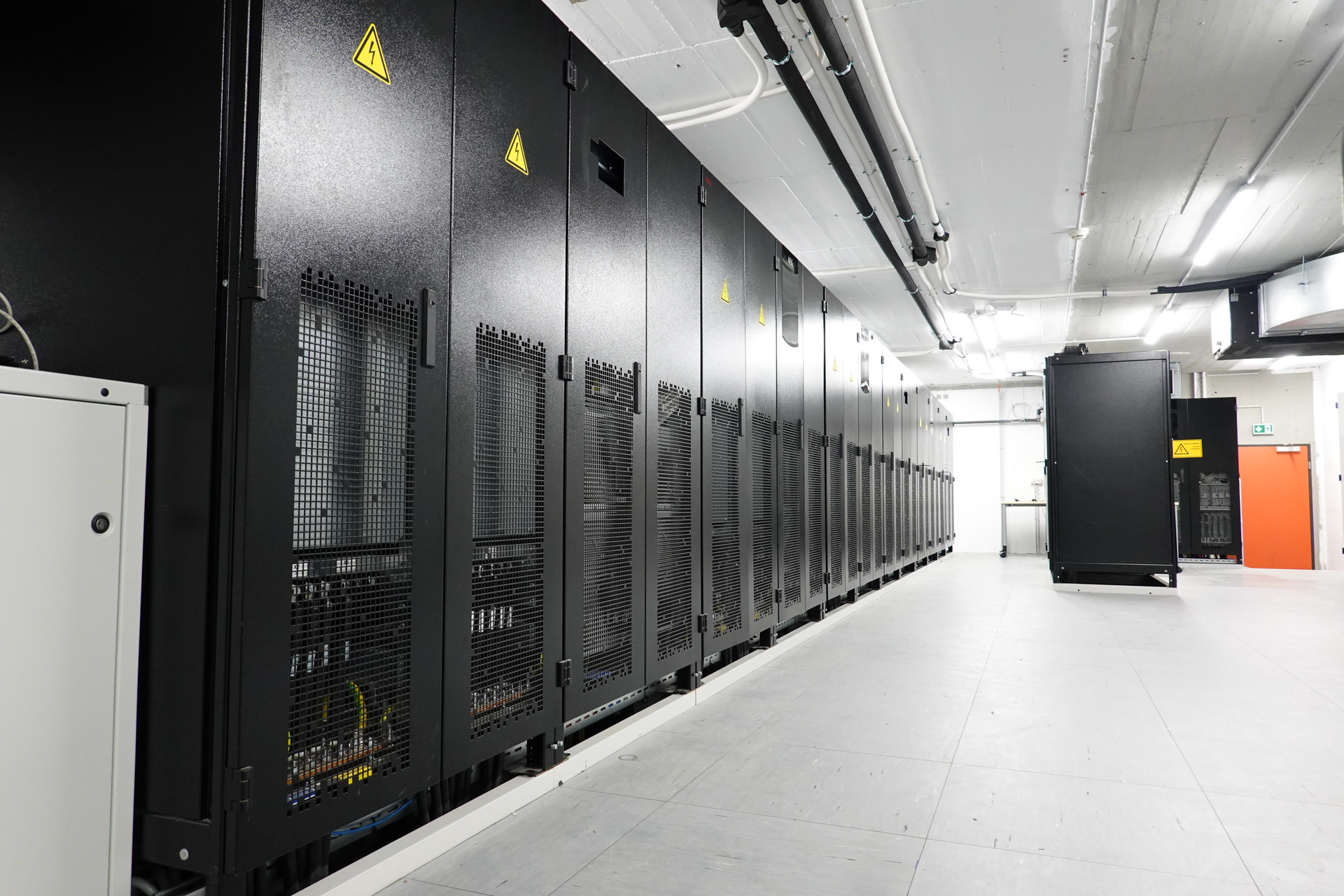
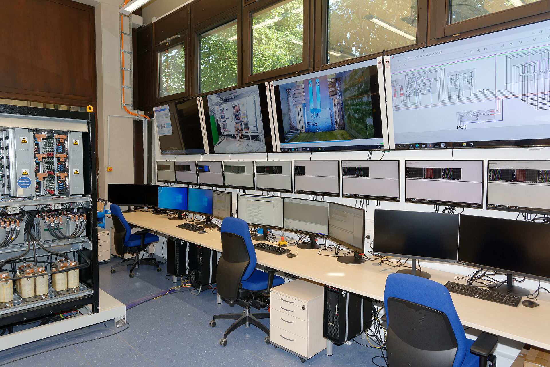
In addition to the fundamental frequency, harmonics, distortions and voltage amplitudes up to 390 V from neutral can be modulated. Fig. 4 shows the control room and Fig. 5 the inverter cabinets.
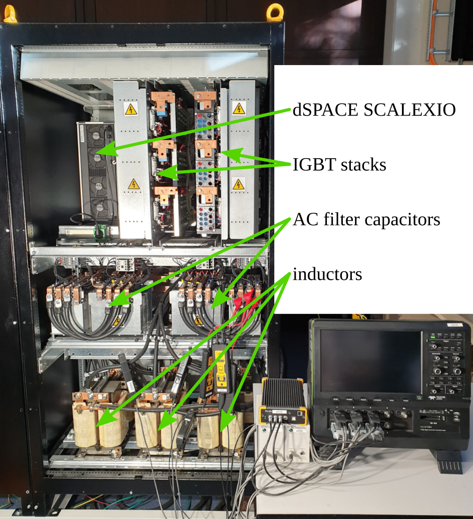
Each grid node is a three-phase, four-wire inverter with a three-level IGBT switching topology and output filters. The output filters have configuration options for L-type, LC-type or LCL-type, where AC filter capacitors are available for 50 Hz and 400 Hz operation.
Two grid-nodes are placed into one cabinet each, schematically shown in Fig. 3.
The converters are operated with direct IGBT-control from the FPGA component of dSPACE rapid control prototyping systems.
Fig. 6 shows one back-to-back inverter.
Images
Explanation Video of the Microgrid Laboratory
The research project was funded and supported by the European Regional Development Fund within the framework of the Northrhine-Westphalian initiative 'Forschungsinfrastrukturen'
Galery

Erklärfilm des Microgrid-Labors


Der Aufbau des Microgrid-Labors wurde gefördert vom Europäischen Fonds für regionale Entwicklung und das Land Nordrhein-Westfalen im Rahmen des Förderprogramms 'Forschungsinfrastrukturen'
Contact:

Research Associate
Office: E4.324
Phone: +49 5251 60-2189
E-mail: schmies@lea.uni-paderborn.de