
Control Design for Wind Power Generators
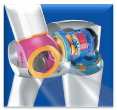
The extension of renewable energy sources has become one of the main efforts of our energy policy nowadays. In the field of wind power these efforts concentrate on the setup of new wind parks and the substitution of older wind turbines by more powerful ones. Today the generators for wind power plants have reached a power class from two to six megawatts. Although the doubly-fed asynchronous generator has been established in that application field, the permanent magnet synchronous generator with embedded magnets becomes more and more important due to its high power density. This type of generator allows a variable speed operation, does not require an energy transfer via collector rings in the rotor and can be driven without a gear if the machine’s pole pair number is high enough. Due to the back-to-back inverter structure which is separated by a DC link it is not necessary to synchronize the synchronous machine with the line voltage during the startup process as it has to be done with the asynchronous power generator where its stator coils are directly connected to the grid. (1), (5)
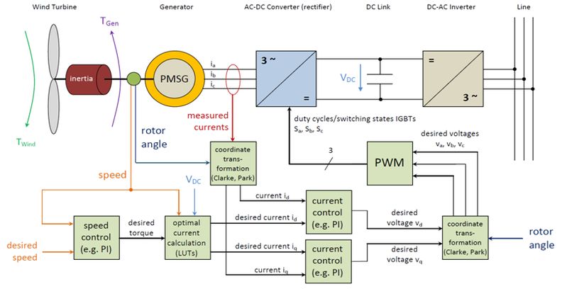
As part of an industry project a control structure for a permanent magnet synchronous generator with embedded magnets for the use in wind turbines has been developed. Apart from the control design stage the research focus was on the choice of low-loss operation points and the detection of critical states in generator and inverter in order to ensure a safe shut down of the drive. The control system consists of a cascaded speed control loop containing a subordinate current control loop. This control structure allows a wide operating range by passing over into the field weakening mode as soon as the desired speed exceeds the nominal angular velocity of the machine. The description and the control design of the machine have been accomplished in the rotor-fixed coordinate system. The PWM signals with desired duty cycles generated by the controller are transformed in the three-phase system to drive the machine inverter. The resulting pulse pattern feeds the synchronous machine. Figure 2 shows the whole control structure of the generator side. (2), (3), (4)
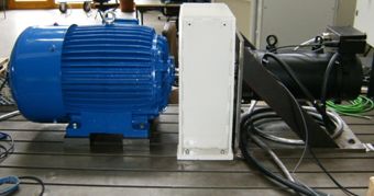
The designed control and the drive system have been built up in MATLAB/Simulink and tested successfully. The control module has then been implemented on a rapid control prototyping board by dSPACE and has been put into operation on a complete test bench, including a PM synchronous machine (50 kilowatts), an asynchronous machine (45 kilowatts) as load machine and the required inverters for the two machines. The linking and the feed-in to the grid have been managed by an autonomous DC-AC inverter. The development of the feed-in control was not part of that project. Figure 3 shows the machine unit consisting of the load machine (blue) and the synchronous generator (black).
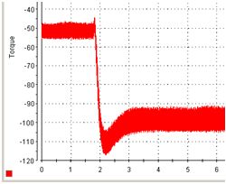
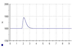
To validate the developed control system several torque steps at different speeds were executed. The two following plots show the disturbance behavior of the controller. The desired speed value has been set to 1800 rpm. The load torque of the asynchronous machine which represents the wind strength has been abruptly doubled from -50 Nm to -100 Nm. After a short acceleration phase the controller initiates a higher current flow to match with the load torque and to adjust the desired speed of 1800 rpm again.
References:
| [1] | E. Hau Windkraftanlagen – Grundlagen, Technik, Einsatz, Wirtschaftlichkeit Springer, 4. Auflage, 2008 |
| [2] | F. D. Bianchi, H. De Battista, R. J. Mantz Wind Turbine Control Systems Springer, 1. Auflage, 2007 |
| [3] | D. Schröder Elektrische Antriebe – Regelung von Antriebssystemen Springer, 3. Auflage, 2009 |
| [4] | Z. Wang, L. Chang PWM AC/DC boost converter system for induction generator in variable-speed wind turbines IEEE, 2005 |
| [5] | R. Lohde, C. Wessels, F. W. Fuchs Operation of Power Electronic Generator Systems in Wind Turbines Christian-Albrechts-Universität Kiel, 2008 |